Tel: +86 15262904857 E-mail: overseas@jsbaileybridge.com
- All
- Product Name
- Product Keyword
- Product Model
- Product Summary
- Product Description
- Multi Field Search


Views: 0 Author: Site Editor Publish Time: 2026-07-20 Origin: Site


Selecting the right bridge design requires balancing load capacity, span requirements, material costs, and deployment speed. Civil engineers and project planners face difficult choices daily. You must bridge challenging physical gaps without exceeding tight budgets or missing strict deadlines. Solid beam structures often demand excessive raw materials. This bulkiness drives up freight costs and heavily extends construction timelines. You can solve these problems by adopting highly efficient architectural frameworks. The core value of a truss bridge lies in its remarkable strength-to-weight ratio. By interlocking structural members, these spans deliver exceptional stability using significantly less steel. We will unpack the essential physics behind these geometric designs in this comprehensive guide. You will learn how these structures manage dynamic forces over long spans. This specific knowledge helps project planners, engineers, and procurement teams evaluate designs confidently. You can then determine if this structural architecture fits your exact infrastructure, timeline, and compliance needs.
Efficient Load Transfer: Truss bridges function by distributing weight through a network of interconnected triangles, converting dynamic loads into pure tension and compression.
High ROI on Materials: The geometric efficiency allows for significant load-bearing capacity using less material than solid beam alternatives, reducing transportation and fabrication costs.
Modular Adaptability: Specific designs, like the bailey truss bridge, offer rapid, pre-engineered deployment for temporary, emergency, or remote access applications.
Maintenance Trade-offs: While highly durable, the complexity of interconnected nodes requires rigorous, localized inspection protocols to maintain structural integrity and compliance.
You must understand basic geometry to grasp how these structures function. The triangle is the undisputed foundational unit of any truss architecture. Squares and rectangles easily lose their shape when subjected to external pressure. Triangles possess a unique mechanical advantage. They cannot be distorted by stress without physically altering the length of their sides. This inherent rigidity makes them the perfect building block for heavy infrastructure.
Every bridge must safely absorb and redirect two distinct types of weight. First, it must support its own structural mass. Engineers call this the dead load. Second, it must support moving traffic and environmental forces like wind or snow. We refer to this as the live load. A well-designed structural framework absorbs these combined loads simultaneously. It instantly disperses the concentrated weight across the entire interconnected framework. This dispersion prevents any single localized point from bearing the full burden.
The network of triangles manages stress by converting dynamic forces into two primary internal reactions. We can categorize these reactions to understand the bridge's survival mechanics:
Compression: These are powerful forces pushing inward on the structural members. They actively attempt to shorten or crush the material. In most standard designs, the top chords and specific vertical posts handle these compressive forces.
Tension: These are outward-pulling forces stretching the structural members. They actively attempt to lengthen or snap the material. The bottom chords and diagonal ties typically absorb these tensile forces.
Consider a simple analogy for non-engineer stakeholders. Imagine walking across deep, powdery snow in normal winter boots. Your boots concentrate your body weight into a tiny surface area. You will immediately sink into the snow. Now imagine wearing wide snowshoes. The snowshoes do not reduce your actual body weight. Instead, they distribute the exact same pressure over a much wider geometric area. A structural truss works exactly like a giant steel snowshoe. It spreads concentrated pressure out over a massive network to prevent catastrophic localized failure.
You cannot use a one-size-fits-all approach when designing infrastructure. You must match the specific structural variation to your project's strict success criteria. Planners base these critical decisions on target span length, dynamic load limits, and available budget. Let us evaluate the three most common historical and modern design variations.
The Pratt configuration stands out as an engineering classic. In this layout, the vertical members handle the inward pushing of compression. The diagonal members slope toward the center and handle the outward pulling of tension. This specific orientation allows engineers to use thinner, lighter diagonal steel ties. The Pratt design offers highly economical use of expensive steel. It performs exceptionally well for spans reaching up to 250 feet.
The Warren configuration takes a slightly different approach to geometry. It relies on equilateral triangles spanning the length of the structure. The diagonal members alternate continuously between handling tension and compression. This highly efficient layout minimizes total material usage. It is excellent for lighter vehicle loads and supports rapid fabrication. However, the Warren design concentrates immense stress at specific joint nodes under heavy dynamic loads. You must reinforce these nodes carefully.
The Howe configuration essentially mirrors the Pratt layout. Its diagonal ties slope away from the center, meaning they handle compression rather than tension. This forces the vertical members to manage the tension. Historically, builders favored the Howe design because it allowed mixed materials. They often used cheap timber for the massive compression diagonals and expensive iron purely for the vertical tension rods. While historically significant, modern heavy-haul commercial infrastructure rarely utilizes the Howe design today.
Structural Design Evaluation Matrix
Design Type | Compression Members | Tension Members | Primary Use Case |
|---|---|---|---|
Pratt | Verticals and Top Chords | Diagonals and Bottom Chords | Medium spans up to 250 feet; economical steel usage. |
Warren | Alternating Diagonals | Alternating Diagonals | Lighter loads; rapid fabrication and material efficiency. |
Howe | Diagonals and Top Chords | Verticals and Bottom Chords | Mixed-material historic builds; rare in modern highway use. |
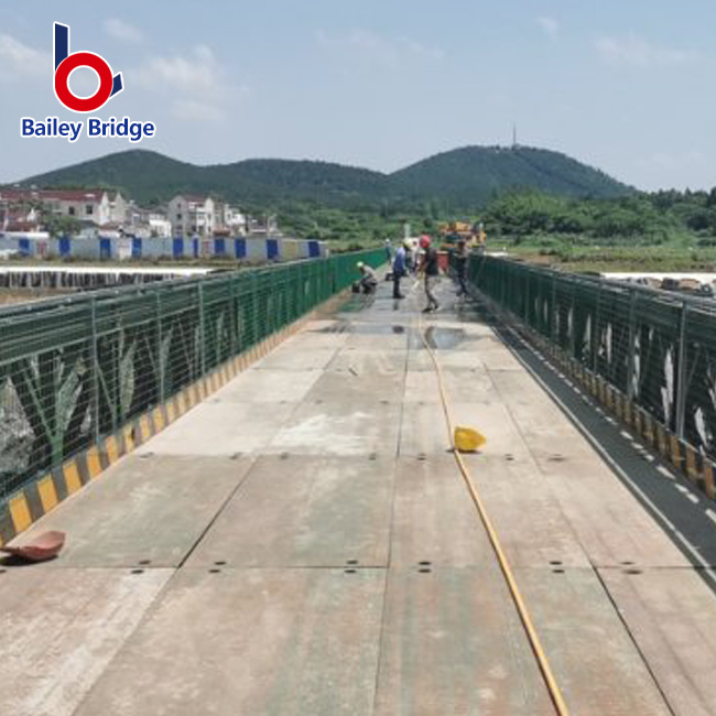
Sometimes project timelines shrink drastically due to emergencies or unexpected logistics hurdles. In these scenarios, you cannot wait months for custom steel fabrication. You need a pre-engineered solution. The bailey truss bridge is a highly famous pre-fabricated, modular steel panel structure. Originating during World War II for rapid troop movement, this ingenious system revolutionized temporary infrastructure. It combines the geometric strength of traditional structural frameworks with the supreme flexibility of modular design.
You should evaluate this modular solution for scenarios requiring immediate, reliable deployment. Typical use cases include urgent disaster relief after floods wash out local infrastructure. Military logistics teams use them constantly to cross difficult terrain. Remote forestry operations rely on them to extract heavy timber over deep ravines. Civil contractors often deploy them as temporary construction bypasses while rebuilding permanent highway infrastructure.
This modular system provides several critical implementation advantages:
No Special Equipment Needed: Field crews can assemble the panels manually using simple tools. You rarely need heavy cranes to push the structure across a gap.
Standardized Parts: The interchangeable steel panels simplify your inventory management. You bypass typical procurement bottlenecks associated with custom-milled structural steel.
Scalable Strength: You can add extra reinforcing panels to the sides to increase the overall weight capacity dynamically.
Reusable Assets: Once your temporary project concludes, you can dismantle the structure, pack it onto trucks, and deploy it elsewhere.
Despite these profound advantages, you must respect the system's operational limitations. Engineers typically deploy these modular units for shorter spans compared to massive permanent installations. They also enforce lower maximum speed limits for crossing traffic. A permanent, custom-engineered framework handles high-speed, heavy-haul interstate traffic better than a temporary modular panel system. You must weigh deployment speed against long-term operational constraints.
Infrastructure planners must ruthlessly justify every capital expenditure. When assessing a structural framework, you must look beyond raw load capacities. You need to analyze the broader commercial advantages. The unique geometry of interconnected triangles delivers exceptional cost-to-span efficiency. You achieve massive strength while severely reducing the overall material volume. Less solid steel and concrete translate directly to much lower raw material costs.
This material reduction triggers a chain reaction of commercial benefits. Because the superstructure weighs significantly less, you pay much cheaper heavy freight charges to deliver it. A lighter bridge also demands significantly reduced foundation requirements. You do not need to pour as much massive concrete for the abutments and piers. This reduction in substructure complexity saves immense labor time and heavy machinery rental costs.
Cost and Efficiency Comparison Chart
Project Metric | Solid Beam Structure | Interconnected Truss Framework |
|---|---|---|
Material Volume | High (Requires thick, continuous webs) | Low (Relies on geometric void spaces) |
Foundation Needs | Heavy (Must support massive dead load) | Lighter (Dead load is highly optimized) |
Freight Expenses | High (Heavy loads require oversized transport) | Lower (Components are lighter and modular) |
Environmental and site impacts represent another major justification factor. Modern construction projects face intense ecological scrutiny. A lighter superstructure requires far less invasive foundation work in sensitive riverbeds or wetlands. By reducing the physical footprint of the abutments and piers, you drastically streamline the environmental permitting process. Less heavy excavation translates to reduced ecological disruption and happier local regulatory agencies.
You also secure excellent long-term durability. Industry durability standards show that galvanized steel frameworks perform exceptionally well over decades. Proper galvanization protects the carbon steel from aggressive moisture and road salts. When you maintain the protective coatings, these installations easily exceed half a century of active service. The strong initial return on investment compounds over a long, reliable operational lifespan.
You cannot make informed engineering decisions without assessing the inherent risks. The primary drawback of any interconnected framework involves the extensive maintenance and inspection realities. These designs rely entirely on hundreds of joints, gusset plates, and heavy bolted connections. Every single structural node represents a potential point of long-term fatigue or localized corrosion.
Debris, moisture, and corrosive road salts easily accumulate in these tight joint spaces. Therefore, you cannot simply inspect the main girders and walk away. The geometric complexity requires highly rigorous, specialized, and routine inspection protocols. Maintenance teams must meticulously check individual gusset plates for microscopic stress fractures. This intensive inspection reality increases your annual operational maintenance budgets.
Clearance restrictions and environmental wind loads also pose implementation risks. Many designs utilize a "through-truss" configuration, where the traffic drives directly through the middle of the steel framework. This specific geometry restricts the total vertical clearance available to the roadway. You must carefully calculate height limits for oversized commercial freight. Furthermore, the extensive network of exposed steel members creates a massive surface area. This large surface area catches significant wind, making the superstructure highly vulnerable to aggressive lateral wind loading. Engineers must calculate and mitigate these aerodynamic forces.
Finally, you must navigate strict regulatory compliance. You must adhere meticulously to local Department of Transportation (DOT) and AASHTO standards. Regulatory bodies strictly govern structural load ratings and mandate specific fracture-critical member redundancies. A fracture-critical member is a single steel component that could trigger a total bridge collapse if it fails. Modern compliance requires you to engineer secondary load paths. These redundancies ensure the structure remains standing even if a primary diagonal tension tie snaps. If you are replacing a historic structure, you must also navigate complex preservation guidelines.
Selecting the optimal bridge framework demands a rigorous evaluation of physics, costs, and project constraints. A truss design remains the optimal choice when you must maximize both span length and load capacity. It succeeds by strictly controlling material weight and raw costs. By leveraging the geometric perfection of the triangle, these structures safely absorb and distribute immense dynamic loads. They offer a highly calculated balance between structural efficiency and capital investment.
When timelines are short or locations are incredibly remote, modular variations provide unmatched value. Prefabricated panel systems allow teams to bypass long custom fabrication queues. They ensure critical access is restored rapidly, safely, and efficiently using basic tools. This modular capability proves invaluable for disaster relief and temporary infrastructure.
You should never finalize a design without expert site analysis. We strongly encourage project stakeholders to consult with licensed structural engineers or experienced modular bridge manufacturers. You should conduct a site-specific feasibility study to map out local environmental loads. Analyze your exact traffic demands and regulatory requirements before breaking ground.
A: A beam bridge resists vertical loads directly through the sheer bending strength of a solid material. It requires thick, heavy girders. A truss design handles weight through a geometric framework of triangles. It efficiently distributes the pressure as tension and compression forces across many lighter interconnected members.
A: With appropriate galvanization and rigorous routine maintenance, a steel framework easily lasts 50 to 75 years. Some historically significant structures have operated for over a century. Lifespan depends heavily on environmental exposure, routine joint inspections, and timely rust mitigation strategies.
A: Yes, under the right conditions. While engineers originally designed them for rapid, temporary deployment, many serve permanently. If properly maintained, galvanized, and kept in lower-traffic or remote access environments, these modular structures can reliably serve local communities for several decades.
A: A steel component is fracture-critical if its sudden failure would cause a portion or the entirety of the bridge to collapse. Modern engineering standards mitigate this severe risk by designing redundant load paths. This ensures the dynamic weight transfers safely to alternative members if one connection fails.
