Tel: +86 15262904857 E-mail: overseas@jsbaileybridge.com
- All
- Product Name
- Product Keyword
- Product Model
- Product Summary
- Product Description
- Multi Field Search


Views: 0 Author: Site Editor Publish Time: 2026-07-28 Origin: Site


Infrastructure projects carry incredibly high stakes. Modern builders must carefully balance heavy load capacities, tight site constraints, strict budgets, and essential long-term durability. Theoretical models studied in academic settings often look perfect on paper. However, they frequently differ wildly from the demanding realities of commercial civil engineering. In the field, a single miscalculation can trigger severe delays, massive budget overruns, or catastrophic structural failure. Planners need practical, field-tested solutions rather than abstract theories to keep public users safe.
This guide provides a comprehensive, decision-stage blueprint tailored for project managers, developers, and municipal planners. You will discover exactly how to evaluate complex structural designs and make informed material choices. We will also explore efficient procurement methods to guarantee a fail-safe, highly resilient build from day one.
Structural Integrity: The strength of a truss bridge relies entirely on efficient triangulation, effectively distributing dead, live, and environmental loads across tension and compression members.
Design Variability: Choosing between Pratt, Howe, or Warren trusses dictates material efficiency and span capabilities based on specific project needs.
Modular Efficiency: Utilizing pre-engineered systems, such as a bailey truss bridge, dramatically reduces deployment time and implementation risks without sacrificing load ratings.
Compliance & ROI: Long-term success requires strict adherence to regional engineering standards (e.g., AASHTO) and strategic vendor selection to minimize lifecycle maintenance.
Every engineering project begins by defining the core business problem. Over-engineering a structure wastes valuable municipal or private budgets. Conversely, under-engineering invites catastrophic liability and endangers lives. Your ultimate goal is pure structural optimization. You need a design performing reliably under maximum stress without inflating material requirements.
The foundation of this optimization lies in the power of triangulation. Rigid triangular units form the backbone of a strong truss bridge. Unlike rectangular frameworks, triangles do not distort when subjected to heavy forces. When you apply weight to a rectangle, it easily flattens into a parallelogram. Triangles inherently resist this shearing effect. They lock the geometry in place, transferring applied weight down toward the supporting abutments.
To understand these forces, we must distinguish between tension and compression. Bridge components act together to manage these opposing energies. We can break down the mechanics as follows:
Top Chords: These upper horizontal beams typically handle compression. The weight pushing down from traffic squeezes these members together.
Bottom Chords: These lower horizontal beams handle tension. As the bridge bends slightly under weight, the bottom members stretch outward.
Diagonal Members: These connect the top and bottom chords. They alternate between tension and compression depending on the specific geometric layout.
Engineers must calculate two primary weight categories. Static loads represent the dead weight of the bridge itself, including steel beams, decking, and permanent fixtures. Dynamic loads represent live, moving weights, such as commuter traffic, heavy freight trucks, and pedestrian crowds. However, gravity is not your only enemy. Environmental load considerations play a massive role in initial stress calculations. You must account for lateral wind shear in exposed valleys. You must design for seismic activity in fault zones. In colder climates, you must calculate the exact weight of potential snow and ice accumulation.
Buyers must evaluate different structural configurations to determine which system fits their specific site parameters. No single geometry solves every engineering challenge. You must match the truss type to your span length, load requirement, and material budget. The three most common solutions dominate modern civil engineering.
The Warren configuration utilizes a series of equilateral triangles. This geometry minimizes the total number of structural members needed. By removing vertical beams, it relies entirely on diagonals alternating between tension and compression. It is best for longer spans where you must prioritize weight reduction and material cost-efficiency. It provides excellent rigidity without overwhelming the foundation with excessive dead load.
The Pratt configuration features vertical members and diagonal members sloping toward the center of the span. Under load, the vertical members experience compression, while the diagonal members experience tension. Because steel handles tension exceptionally well but can buckle under intense compression, making the longer diagonal members handle tension is highly efficient. It is best for standard vehicular applications. You will frequently see this layout across highways and municipal waterways.
The Howe configuration looks like a reversed Pratt. The diagonal members slope away from the center. Here, the vertical members experience tension, while the longer diagonal members handle compression. Historically, builders used wood for diagonals and iron for verticals. Today, heavy steel spans utilize this design for specific high-stress applications. It is best for shorter spans facing exceptionally heavy, concentrated load requirements, such as freight rail lines or heavy industrial transport routes.
Below is a quick reference table detailing the primary differences among these three standard structural configurations.
Configuration | Primary Geometry | Force Distribution | Ideal Application |
|---|---|---|---|
Warren | Equilateral triangles | Alternating tension/compression in diagonals | Long spans, material efficiency |
Pratt | Diagonals slope to center | Verticals in compression, diagonals in tension | Standard highway and vehicular bridges |
Howe | Diagonals slope away | Verticals in tension, diagonals in compression | Short spans, heavy rail transport |
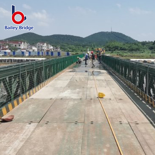
Traditional bridge building often requires custom-built, site-welded structures. This approach demands extensive labor, favorable weather, and long timelines. Today, strategic planners increasingly favor prefabricated modular systems. They offer a highly viable, cost-effective alternative for both temporary and permanent installations.
At the forefront of this modular revolution is the bailey truss bridge. Originally designed by Donald Bailey during World War II for rapid military deployment, this system has evolved into a staple of commercial civil engineering. It is a portable, pre-fabricated structure built from interchangeable high-tensile steel panels. Crews connect these panels using heavy-duty steel pins, completely eliminating the need for complex on-site welding.
When evaluating a modular system, project managers should look at three specific features-to-outcomes dimensions:
Scalability: Standardized parts remain entirely interchangeable. If traffic demands increase years after the initial build, you can reinforce the structure. Adding extra layers or rows of side panels easily increases the load capacity retroactively.
Speed: Crews can assemble these bridges using basic heavy machinery. You do not always need massive, specialized cranes. This dramatically reduces total labor hours, site disruption, and road closure times.
Use Cases: They excel in high-pressure scenarios. They serve as ideal emergency detours following natural disasters. They are perfect for remote mining and logging operations requiring heavy truck access. Furthermore, they function brilliantly as temporary-to-permanent municipal infrastructure.
Selecting the right structural material dictates the lifespan and maintenance routine of your project. We evaluate materials based on raw tensile strength, environmental resistance, and weight. The choice between different grades of steel and aluminum fundamentally changes the engineering approach.
Weathering steel, commonly known as Cor-Ten, provides exceptionally high strength. It intentionally develops a protective rust patina over time. This oxidized layer seals the inner steel from further decay. It requires remarkably low ongoing maintenance, making it ideal for remote or difficult-to-access locations. Galvanized steel takes a different approach. Manufacturers dip the steel components in molten zinc. This creates maximum durability against harsh, corrosive environments. You should strictly specify galvanized components for coastal regions, high-salinity areas, or roads treated heavily with winter de-icing salts.
Structural aluminum offers a distinct alternative. It is remarkably lightweight and naturally corrosion-resistant. It does not rust like untreated steel. However, aluminum yields under lower weight thresholds compared to heavy steel alloys. It serves as an ideal material for pedestrian spans, golf course bridges, or environmentally sensitive zones requiring low-impact installations.
Beyond material chemistry, you must prioritize security and compliance. Engineering is an incredibly strict discipline. You must demand professionally stamped engineering drawings from licensed structural engineers. Adherence to regional load rating standards, such as the AASHTO (American Association of State Highway and Transportation Officials) LRFD framework, remains absolutely non-negotiable. Furthermore, you must verify rigorous weld inspections. Factories should utilize ultrasonic or radiographic testing to confirm every weld penetrates properly without hidden air pockets.
A flawless paper design means nothing if you fail to execute the physical implementation. On-the-ground realities present massive challenges. Project managers must navigate difficult terrain, volatile weather, and complex machinery logistics.
Geotechnical preparation stands out as the most critical risk factor. The strongest steel spans will collapse if the foundation fails. Geotechnical engineers must test soil bearing capacity before pouring abutments. If foundational soil shifts, or if concrete abutments lack proper rebar reinforcement, the entire structure becomes compromised. You must secure the earth before you bridge the gap.
Logistics and transportation introduce another layer of complexity. Moving oversized steel beams to a remote or tight-access job site requires precise coordination. You might need special permits, highway escorts, or specialized multi-axle trailers. In mountainous regions, tight switchback roads can entirely prevent the delivery of long continuous beams. This reality often forces planners to utilize modular panel designs.
Finally, you must select the appropriate launch method. Crane-lift installations are fast but require heavy equipment access directly alongside the embankment. If the terrain is too soft or steep to support a 100-ton crane, you must pivot. Cantilever launching offers a brilliant alternative. Crews assemble the bridge on dry land behind the abutment. They attach a lightweight "launching nose" to the front. Using rollers and heavy machinery, they slowly push the bridge across the gap. This cantilever method is highly common for modular panel systems.
You secure long-term strength during the early procurement and evaluation phase. Choosing a reliable vendor for design and fabrication requires a rigid decision framework. Do not base your decision solely on the lowest initial bid. You are purchasing a critical piece of public infrastructure.
Look for crucial vendor capabilities. A top-tier manufacturer maintains in-house engineering and detailing teams. They should employ AWS-certified welders and readily supply transparent Quality Assurance and Quality Control (QA/QC) documentation. Furthermore, they need a proven track record delivering the specific truss type you require. A vendor specializing in lightweight pedestrian walkways might lack the expertise to fabricate a heavy-haul logging route.
Watch out for immediate red flags during the consultation process:
Vendors offering vague load capacity guarantees instead of certified engineering calculations.
Firms lacking site-specific customization, trying to force a generic product onto a unique topography.
Suppliers failing to provide comprehensive, easily understandable installation manuals and on-site guidance.
Your immediate next-step action is gathering critical data. Advise your team to prepare a preliminary site survey. Document the exact span length, the required load rating, and all site access constraints. Presenting this clear data to a prospective manufacturer streamlines the consultation and yields highly accurate preliminary quotes.
Building a strong, reliable spanning structure requires a careful synthesis of multiple engineering disciplines. You must choose the correct geometric configuration to manage tension and compression. You must select site-appropriate materials capable of withstanding local environmental threats. By utilizing efficient deployment methods, such as modular construction, you can significantly reduce site disruption and labor hours.
Never forget that ultimate long-term strength is secured during the procurement phase. Thoroughly vetting your manufacturing partner prevents catastrophic failures and minimizes long-term maintenance burdens. You cannot afford shortcuts when public safety and heavy logistics rely on your project.
Take action today to protect your infrastructure investment. Contact a specialized engineering consultant or request a site-specific load evaluation and detailed quote from a certified manufacturer.
A: Assembly times depend heavily on the total span length and site conditions. However, rapid deployment is a primary advantage. A trained crew using basic heavy machinery can often assemble and launch a standard single-span modular structure in just a few days to a couple of weeks. This dramatically outpaces traditional custom-welded builds.
A: A single clear span without intermediate supports can typically range from 50 to 300 feet, depending on the specific geometry and material weight. However, you can extend the total length indefinitely by utilizing multi-span configurations. By placing intermediate concrete piers in the waterway or valley, you can connect multiple spans seamlessly.
A: Engineers use advanced software running finite element analysis (FEA) to simulate forces. They calculate dead loads (the structure's weight) against dynamic live loads (traffic and environmental factors). They must strictly ensure these calculations comply with regional transportation codes, such as the AASHTO LRFD specifications, to certify the exact weight limits.
A: Concrete beams generally have lower upfront material costs. However, steel modular systems offer massive speed advantages. When you calculate reduced labor hours, minimal heavy crane rentals, and immediate deployment capabilities, pre-engineered steel structures often become the more economical choice. Steel is especially cost-effective for remote sites where pouring massive concrete volumes is impractical.
