

Views: 0 Author: Site Editor Publish Time: 2026-09-16 Origin: Site


Project managers, military engineers, and infrastructure developers face critical delays when evaluating temporary or semi-permanent bridge structures. Selecting the wrong configuration risks structural failure. It also invites compliance violations or extensive procurement delays. The foundational relationship in modular bridging is the inverse correlation between span length and live load capacity. Understanding how different panel types and truss configurations alter this equation is vital for accurate engineering. You need reliable ways to match heavy equipment requirements against structural realities. This article provides a rigorous evaluation framework comparing standard modular types. Readers will learn structural limitations and specific configurations required to meet Military Load Classifications or commercial highway standards. We break down truss matrices, panel types, and material limits to guide your next deployment. Review these engineering baselines carefully. They help you scale load limits using advanced structural arrangements securely.
Inverse Relationship: As span length increases, the dead load of the structure consumes a higher percentage of the total bearing capacity, exponentially reducing the permissible live load.
Panel Variations: The shift from traditional Compact 100 (CB100) to Compact 200 (CB200) steel bailey bridge panels offers an average 33% increase in yield strength and greater span capabilities.
Configuration Multipliers: Load and span limits are engineered by combining trusses and storeys (e.g., Single-Single vs. Triple-Double), allowing for modular scalability based on exact site requirements.
Compliance Realities: Evaluators must factor in material fatigue, pin tolerance, and local regulatory standards (e.g., AASHTO or Eurocode) alongside baseline manufacturer capacity claims.
Every modular bridging project starts with a strict physical limit. A structural system spanning a wide gap must support its own self-weight before it can support external traffic. Engineers call this self-weight the dead load. The crossing vehicles represent the live load. As you increase the span length, you must add more steel panels to cross the gap. This directly increases the dead load. Consequently, the dead load consumes a higher percentage of the total bending moment capacity. This trade-off exponentially restricts the allowable live load.
You cannot evaluate load capacity using arbitrary weight claims. Engineers frame this evaluation through standardized metrics. For military applications, teams rely on the Military Load Classification (MLC) system. The MLC system defines distinct load classes for wheeled and tracked vehicles. It accounts for axle spacing, footprint area, and vehicle weight. For standard commercial highway loads, evaluators use the HL-93 design load standard. HL-93 criteria ensure structures safely handle heavy multi-axle freight traffic.
Theoretical maximum spans often assume ideal, static conditions. However, real-world evaluation demands strict safety factors. Moving vehicles generate dynamic forces. Sudden braking creates severe longitudinal impact loads. High winds apply massive lateral pressure against the bridge panels. A standard bailey bridge accommodates these forces through specialized sway braces and transoms. You must heavily discount theoretical limits to account for dynamic real-world environments.
Here is an illustrative chart showing how allowable live loads drop as span distances increase under standard single-lane configurations.
Span Length (Meters) |
Configuration Model |
Estimated Max Live Load (Tons) |
Primary Limiting Factor |
|---|---|---|---|
15m |
Single-Single (SS) |
~30 - 40 Tons |
Shear stress near abutments |
30m |
Double-Single (DS) |
~40 - 50 Tons |
Bending moment at mid-span |
45m |
Double-Double (DD) |
~35 - 45 Tons |
Dead weight accumulation |
60m |
Triple-Double (TD) |
~25 - 35 Tons |
Severe dead load dominance |
Selecting the right base panel dictates the entire project outcome. Manufacturers primarily produce two distinct variations of modular bridge panels. Understanding their exact dimensions and structural behaviors prevents costly misapplications.
The CB100 represents the original modular design lineage. These panels feature standard dimensions of 3.048 meters in length and 1.448 meters in height (roughly 10 feet by 5 feet).
Span and Load Profile: The CB100 works best for short-to-medium spans. Engineers typically deploy them for gaps up to 50 meters. They handle moderate loads effectively.
Decision Lens: This panel type offers high cost-effectiveness. It excels in highly constrained deployment sites. You will often see them used for pedestrian crossings, light-duty traffic diversions, or remote logging roads.
Common Mistake: Project managers sometimes push CB100 panels beyond their intended spans to save money. This invites excessive mid-span deflection and accelerates pin hole elongation.
Modern heavy infrastructure demands higher yield capabilities. The CB200 panel answers this need. It measures 3.048 meters in length but increases the height to 2.134 meters (roughly 7 feet).
Span and Load Profile: The taller web depth significantly increases the bending moment resistance. Upgrading to a steel bailey bridge utilizing CB200 panels allows single spans up to 80 meters. The thicker steel members support heavier high-clearance traffic.
Decision Lens: The CB200 serves as the modern industry standard for heavy commercial logistics. Mining operations rely heavily on them. They easily support multi-lane highway diversions.
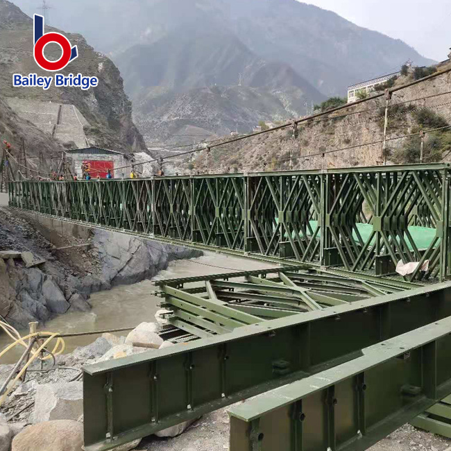
You do not buy a fixed-capacity bridge. You engineer the capacity on-site. Load and span limits scale modularly by combining adjacent trusses and stacking vertical storeys. Engineers use a specific nomenclature to describe these matrices.
The naming convention always lists the number of side-by-side trusses first. It lists the vertical storeys second. For example, a "Double-Single" features two trusses bolted side-by-side on each side of the deck, stacked one storey high. Reinforcing the structure in this manner directly solves specific load and span problems.
The SS configuration uses one panel line per side. It serves very short spans, typically maxing out around 15 meters. It supports light vehicle weights. Teams choose the SS matrix for its incredible assembly speed. A small crew can launch an SS bridge in hours. However, it offers the lowest overall load capacity.
When span lengths increase to the 20-meter to 40-meter range, dead load becomes more prominent. Evaluators often deploy baily bridges in DS or DD configurations here. Adding a second adjacent truss dramatically jumps the bending moment resistance. The DD configuration stacks a second level of panels on top. This dramatically stiffens the structure. It perfectly balances assembly speed against the need to move standard commercial freight.
Extreme operations require extreme configurations. The TD matrix utilizes three side-by-side trusses stacked two storeys high. Engineers use TD and TDR (Reinforced) setups for maximum spans approaching 80 meters. They also use them to support extreme heavy-haul operations. Main battle tanks and heavy mining articulated dump trucks require this level of support.
While the load capacity hits maximum levels, the drawbacks are significant. TD configurations require specialized erection equipment. They demand much larger launching areas on the near bank. Furthermore, they generate significantly higher shipping volumes due to the massive part count.
Engineering the trusses only solves half the problem. Procurement teams must scrutinize the finer technical dimensions to ensure long-term viability. Material choices directly influence the dead weight penalty.
Decking selection drastically alters bridge performance. Standard steel orthotropic decks offer superior durability. They provide exceptional strength-to-weight ratios. Orthotropic designs use closed steel ribs welded to a top plate. This distributes wheel loads highly efficiently while keeping dead weight low.
Conversely, timber decking provides a cheaper upfront alternative. However, timber adds substantial dead weight. It also demands frequent replacement under heavy traffic. Additionally, you must consider deck width. Widening the structure to accommodate two lanes doubles the deck weight. It also exposes a larger surface area to lateral wind loads. Widening a bridge directly reduces its maximum permissible span length.
Raw steel quality defines structural safety. Evaluate the necessity of high-yield steel grades like Q345 or Q460 carefully. High-yield structural steel resists permanent deformation under immense stress. You must warn your procurement teams against cheaper, lower-grade materials. Low-grade panels might easily pass a static load test on day one. However, they rapidly fail under high-cycle fatigue. Continuous loading and unloading from heavy truck traffic cause microscopic stress fractures in inferior steel.
Shortlisting criteria must prioritize regulatory alignment. Check for independent certifications. Valid ISO manufacturing standards and CE marks prove factory quality control. Furthermore, any bridge intended for public traffic must comply with national design codes. Ensure the engineering models align strictly with AASHTO LRFD standards or Eurocode regulations.
Theoretical designs eventually meet dirt and mud. You must prepare for site-specific physical constraints. Poor launch planning ruins project timelines.
Engineers rarely lift heavy modular structures into place with cranes. Instead, they utilize the cantilever launch method. Crews assemble the bridge on the near bank on roller beds. They attach a lightweight "launching nose" to the front. A bulldozer or excavator pushes the entire assembly across the gap.
This method requires a massive staging footprint. You need a flat staging area on the near bank roughly equal to the length of the bridge being pushed. If you face constrained mountainous terrain, this footprint requirement may disqualify certain long-span designs entirely.
Modular panels connect using heavy steel pins. A 60-meter bridge contains dozens of pinned joints. Every joint has a tiny machining tolerance. Over long spans, this cumulative tolerance causes structural "sag" or deflection. High-cycle traffic accelerates pin wear. Regular inspection protocols must measure mid-span deflection to ensure the structure remains within safe operational limits.
Procurement teams should follow a strict evaluation framework before engaging manufacturers. Use this step-by-step logic:
Define the exact maximum gap width: Measure from firm bearing surface to firm bearing surface, not just the water edge.
Identify the heaviest single vehicle load: Distinguish between maximum axle load and total gross vehicle weight. Axle load dictates deck strength; gross weight dictates truss configuration.
Determine required lane width and lifespan: Specify if the project is temporary (months) or permanent (decades).
Request site-specific engineering data: Ask shortlisted manufacturers for detailed general arrangement (GA) drawings based strictly on the first three variables.
Acknowledge the Matrix: A modular bridging system is never a one-size-fits-all product. The inverse relationship between dead load and live load governs everything.
Align Configurations to Reality: Your final load limit relies entirely on your selected panel type (CB100 vs CB200) and your chosen truss-storey configuration.
Demand Transparent Data: Prioritize manufacturers who supply transparent, site-specific engineering calculations. Discard vendors who only provide generic, best-case-scenario capacity charts.
Plan for the Launch: Secure adequate staging ground footprint early. The cantilever method dictates your site preparation needs.
Take Action: Contact a qualified technical sales engineering team today. Provide your specific gap measurements, target MLC requirements, and lane widths to receive a custom configuration assessment.
A: The theoretical maximum for a standard un-piered single span is approximately 80 meters. Engineers achieve this using Compact 200 panels in a Triple-Truss, Double-Storey Reinforced (TDR) configuration. However, pushing to this 80-meter extreme drastically increases dead weight, which significantly reduces the permissible live load capacity.
A: Yes. They regularly handle heavy armored units. However, accommodating main battle tanks requires strict adherence to Military Load Classification (MLC) ratings. Tanks usually demand MLC-70 or higher ratings. Achieving this across a moderate gap typically requires a Triple-Double (TD) or reinforced configuration to safely handle the track footprint and weight.
A: Expanding from a single-lane to a double-lane deck drastically increases the structural dead weight. It requires much longer and heavier transoms (cross-beams). It also exposes a wider profile to lateral wind stresses. Consequently, double-lane structures have notably shorter maximum span limits compared to single-lane models.
A: Yes. Load limits account for fatigue life. A temporary bridge can often safely handle peak maximum loads over short durations. Permanent installations require stricter, reduced safety margins. This protects the steel members from high-cycle fatigue caused by continuous, cyclic loading over decades of daily traffic.
