Tel: +86 15262904857 E-mail: overseas@jsbaileybridge.com
- All
- Product Name
- Product Keyword
- Product Model
- Product Summary
- Product Description
- Multi Field Search

Views: 0 Author: Site Editor Publish Time: 2026-07-03 Origin: Site


Short-span crossings present unique daily challenges for modern civil engineering. Planners often face disproportionate mobilization costs when bridging gaps under 60 meters. Traditional concrete construction demands prolonged environmental permitting. Heavy machinery footprints also force extended site closure times. You need a more efficient alternative to keep projects moving.
The Compact 321 bridge system bridges this exact operational gap. It successfully balances rapid deployment requirements and heavy-duty load-bearing capacities. Engineering teams use it to bypass the slow pacing of conventional builds. We designed this guide to help project managers and civil engineers objectively evaluate this technology.
You will learn how to integrate these structures into a modern infrastructure portfolio. We explore practical deployment strategies, structural mechanics, and clear performance limits. This evaluation provides the actionable data you need for better site planning. Read on to master the deployment of these robust structural solutions.
Accelerated Deployment: Pre-engineered modular components eliminate curing times and reduce heavy machinery dependencies, allowing for assembly in days rather than months.
Scalable Load Capacity: Truss configurations can be mathematically scaled (e.g., single-lane to multi-lane, single-truss to multi-truss) to meet specific AASHTO or military load classifications.
Predictable Cost Modeling: Standardized parts reduce supply chain volatility, offering higher financial predictability compared to custom-designed conventional spans.
Deployment Realities: Success heavily depends on precise abutment preparation and controlled cantilever launching techniques; it is not a "drop-in" solution without engineering oversight.
Civil engineers face strict logistical barriers when planning short-span crossings. Pouring custom concrete spans under 60 meters creates severe financial inefficiency. You must transport heavy cranes to remote locations. You must also build custom formwork for a relatively small structural footprint. This traditional approach ties up valuable heavy equipment for weeks. Equipment rentals and specialized labor teams quickly drain project resources. Planners must seek methods minimizing these heavy mobilization constraints.
Environmental compliance creates another massive bottleneck for short spans. Traditional bridge construction requires extensive in-water work. Driving piles or pouring piers directly in riverbeds triggers strict regulatory scrutiny. Environmental agencies often require months to issue these permits. Prolonged in-water work risks aquatic habitat disruption. Furthermore, extended road closures create severe friction within local communities. Detours disrupt local commerce and emergency response times. You escalate project risk whenever you block critical local pathways for extended periods.
Project managers also face the temporary versus permanent dilemma. Many industries only require access for two to five years. Logging operations frequently shift to new forest sectors. Mining companies abandon access roads once they deplete local mineral veins. Disaster relief teams need immediate, functional passage during recovery phases. Building permanent concrete structures for these temporary needs wastes enormous capital. The industry needs a solution combining permanent-level strength and temporary-level agility.
Heavy Machinery Logistics: Moving high-tonnage cranes to remote sites often requires reinforcing the approach roads first.
Environmental Permitting Timelines: In-water concrete pouring forces environmental agencies to enforce strict mitigation protocols.
Community Friction: Closing a local route for six months damages public goodwill and political support.
The Lifecycle Mismatch: Building a 50-year concrete bridge for a 3-year mining operation demonstrates poor resource allocation.
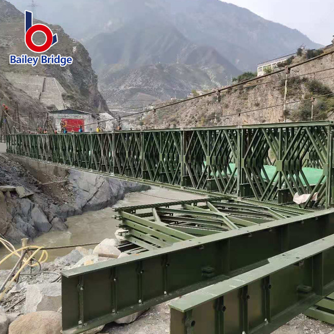
We must examine the engineering pedigree behind these modular structures. The system represents a modernized iteration of the proven Bailey bridge concept. Early military engineers developed the original Bailey design for rapid wartime deployment. Today, engineers utilize high-yield steel to upgrade the entire framework. This modern alloy allows the panels to carry significantly heavier commercial loads. The entire design revolves around standardized assembly. Crews pin identical components together to form rigid, continuous spans.
Understanding the component anatomy helps planners visualize the assembly process. The main longitudinal trusses rely on standardized steel panels. Each panel measures approximately three meters long. Workers align these panels end-to-end and secure them using heavy steel pins. Transoms cross between the main trusses to provide transverse support. These heavy transverse beams ultimately support the deck plates. The deck plates can consist of solid steel or heavy timber. They capture wheel loads and distribute the axle weight efficiently into the transoms.
Standardized Panels: The core three-meter truss building blocks. They feature precisely drilled pin holes for fast connection.
Transoms: The cross-beams resting on the lower chords of the panels. They dictate the roadway width.
Deck Plates: The riding surface. Steel plates offer high durability. Timber decking offers lighter dead weight.
Bracing Components: Sway braces and rakers stabilize the entire frame against lateral wind forces.
Configuration flexibility stands out as the greatest mechanical advantage. Engineering teams can mathematically scale the trusses. They manage dead load and live load requirements by stacking panels differently. You do not need to redesign the bridge for heavier trucks. You simply add more standard panels to the truss line. A "Single-Single" configuration means one panel wide and one tier high. A "Double-Double" configuration means two panels wide and two tiers high. This modular stacking scales the bridge capacity instantly.
Configuration Type | Truss Lines (Per Side) | Tiers (Height) | Typical Use Case |
|---|---|---|---|
Single-Single (SS) | 1 | 1 | Pedestrian access, light vehicles, short gaps. |
Double-Single (DS) | 2 | 1 | Standard highway traffic, medium-length logging roads. |
Double-Double (DD) | 2 | 2 | Heavy industrial haul trucks, extended spans over 30m. |
Triple-Double (TD) | 3 | 2 | Extreme axle loads, mining equipment, maximum spans. |
You must match your structural selection to required operational metrics. The Compact 321 steel bridge easily meets standard American Association of State Highway and Transportation Officials (AASHTO) classifications. Engineers routinely configure these structures for HS20 or HL-93 highway loads. The system also accommodates standard wheeled and tracked military classifications. You must verify the maximum anticipated axle load before selecting your truss configuration. A heavy tracked excavator applies stress differently than a wheeled semi-truck.
Pinned-joint systems exhibit specific fatigue and deflection tolerances. You must objectively understand these limits. Modular steel trusses deflect more under live loads compared to continuous poured concrete. The bridge will visually bounce or flex as heavy trucks cross. This deflection remains entirely safe and mathematically calculated. However, you must account for this movement in your approach designs. The transition plates must accommodate the vertical flex. Recognizing these different deflection profiles prevents unnecessary alarm during initial load testing.
Corrosion protection directly impacts the lifecycle of the installation. You must evaluate the site conditions before ordering components. Inland sites in dry climates often tolerate standard industrial paint coatings. However, coastal environments present severe salt-spray hazards. High-humidity jungle environments also accelerate steel degradation. In these aggressive environments, you should specify hot-dip galvanization. Galvanized steel resists rust for decades without requiring repainting. This protection layer prevents the critical connection pins from seizing up over time.
Calculate exact axle loads before choosing a panel configuration.
Account for dynamic braking forces on steep approach grades.
Specify hot-dip galvanized components for any marine or coastal deployment.
Install flexible transition ramps to absorb natural truss deflection.
Ignoring the weight of the decking when calculating total dead load.
Applying rigid concrete design standards to flexible pinned steel structures.
Failing to inspect pin tolerances after major seismic or flood events.
Successful deployment heavily depends on rigorous site preparation. You cannot treat a modular bridge system as a simple "drop-in" product. The abutments require exact engineering. They must remain structurally sound and perfectly level. Teams must install robust bank seat plates on both sides of the gap. These heavy steel plates distribute the enormous point loads of the bridge ends into the ground. If the ground settles unevenly, the truss will experience severe torsional stress. Differential settlement can permanently warp the standard panels.
The cantilever launch method defines the installation process. Teams rarely lift the fully assembled bridge into place. Instead, they assemble the structure on the home bank. They construct a lightweight launching nose on the front. This temporary nose frame reaches across the gap first. Crews push the entire assembly forward over heavy steel rollers. The nose lands on the far bank rollers. The team then continues pushing until the main heavy bridge crosses the gap entirely. They then dismantle the nose.
This cantilever process carries specific operational risks. Engineers must calculate precise counterweights for the rear of the bridge. If the team miscalculates the center of gravity, the bridge will tip forward into the river. Roller binding presents another common risk. If the alignment shifts slightly, the steel chords will jam against the roller flanges. You must employ a highly disciplined launch commander. This single individual controls the pushing pace and monitors the roller alignments simultaneously.
We must also unpack the common assumptions regarding labor and equipment ratios. Project managers love these systems because they transition away from high-tonnage cranes. You can typically use mid-size excavators to lift the individual panels. Manual pinning teams physically connect the components. Many planners assume they can use completely unskilled labor. This assumption proves dangerous. While the basic panel assembly seems simple, maintaining perfect structural alignment requires extreme precision. You absolutely need an experienced foreman overseeing the hand-tool crews.
Phase 1: Rollers and Bank Seats. Survey the abutments and secure the launching rollers perfectly square.
Phase 2: Nose Assembly. Build the lightweight skeletal frame designed to span the gap first.
Phase 3: Main Assembly and Push. Pin the heavy panels behind the nose and advance the structure incrementally.
Phase 4: Landing and Jacking. Receive the nose on the far bank, jack the bridge up, remove the rollers, and lower it onto the permanent bearings.
Civil engineers must utilize clear shortlisting logic when evaluating crossing solutions. The Compact 321 proves optimal when speed remains your highest priority. It excels when remote access prevents heavy crane deployment. The inherent reusability of the components makes it a superior financial choice for temporary mining or logging roads. However, you should look elsewhere if your project demands high architectural aesthetics. You should also rely on conventional methods for ultra-long continuous spans exceeding 60 meters.
You can take several immediate action steps to advance your evaluation phase. First, conduct a thorough geotechnical survey of your proposed abutment locations. The soil must support the concentrated point loads. Second, calculate your exact maximum live axle loads. Do not just estimate total vehicle weight. Finally, contact specialized manufacturers to request configuration-specific load-rating charts. These charts will clearly dictate whether you need a Double-Single or a Double-Double truss configuration for your specific site.
A: The safe operational limit typically maxes out around 51 to 60 meters. This limit depends heavily on your target load class. As you increase the span length, you must add more truss lines to support the center. Eventually, the dead weight of a massive Triple-Double configuration becomes prohibitive to launch safely.
A: Yes, many jurisdictions approve them for permanent public highway use. However, you must verify compliance with local permanent design codes. Permanent installations usually require specific anti-skid decking upgrades. Engineers must also run detailed fatigue-life calculations to ensure the pins withstand decades of continuous daily traffic.
A: A realistic baseline requires a dedicated crew of 8 to 12 trained workers. You will need a 20-ton excavator or a small rough-terrain crane to lift the panels into position. The crew primarily uses standard heavy hand tools, sledgehammers, and alignment bars to secure the connection pins.
A: The systems differ primarily in panel dimensions, steel strength, and chord depth. The older 100 system uses lighter steel and shorter panels. The 200 system increases panel depth for better load capacity. The 321 system utilizes optimized high-yield steel and wider dimensions, offering superior heavy-duty performance for modern truck axles.

