Tel: +86 15262904857 E-mail: overseas@jsbaileybridge.com
- All
- Product Name
- Product Keyword
- Product Model
- Product Summary
- Product Description
- Multi Field Search


Views: 0 Author: Site Editor Publish Time: 2026-07-24 Origin: Site


Infrastructure projects stand or fall on initial structural choices. Engineers must carefully evaluate geometry and physics before breaking ground. Assessing structural viability for infrastructure projects requires balancing load capacity, span length, and budget. Relying on basic beam structures for inappropriate spans leads to structural failure or excessive material costs.
Transitioning from theoretical physics to applied project management clarifies this challenge. We examine why the geometric mechanics of a truss bridge allow for greater load-bearing capacity. You will discover exactly when to specify it over a standard beam design. We outline specific deployment strategies and risk assessments for your next major build. Project managers can use these insights to streamline procurement and ensure long-term structural integrity.
Force Distribution: Truss bridges utilize interconnected triangles to convert bending moments into pure tension and compression, eliminating the central weakness inherent in beam bridges.
Span Scalability: While beam bridges suffer from exponential dead-load increases over long distances, truss structures maintain a high strength-to-weight ratio, allowing for significantly longer unsupported spans.
Deployment Versatility: Pre-engineered modular options (such as the bailey truss bridge) provide rapid implementation capabilities for both temporary and permanent infrastructure needs.
Trade-off Reality: The enhanced strength of a truss design comes with increased fabrication complexity and elevated maintenance requirements due to a higher volume of structural joints.
Solid structures face severe physical limitations over long distances. We must first understand the mechanics of a bending moment. When heavy loads press down on a simple span, the structure bends. Compressive forces concentrate heavily on the top edge. These forces push the material inward. Simultaneously, tensile forces stretch the bottom edge outward. The material actively pulls apart.
This dynamic creates a major structural flaw. A "dead zone" forms directly in the middle of the span. Engineers call this the neutral axis. Material located along this central plane experiences almost zero stress. It strictly adds heavy dead weight but provides minimal structural benefit. You cannot simply build thicker spans to cross wider rivers. The structure eventually collapses under its own massive weight. This strict limitation defines unsupported span length.
Skeletal geometry solves this dead-weight problem completely. Triangular webbing redistributes downward loads axially. Forces travel straight along the steel members. The geometric shapes convert bending forces into pure tension and compression. No single piece bends. They either push together or pull apart.
This design actively engages all material in the structure. The intersecting triangles force every steel beam to share the load. This prevents isolated stress concentration. A heavy freight train might press down on one specific section. The surrounding triangles instantly pull and push against each other. They transfer the localized stress safely into the concrete abutments. Triangles cannot deform. You cannot change their shape without physically breaking one of the sides. This mathematical rigidity creates unmatched stability.
Project engineers must calculate both dead load and live load. Dead load represents the physical weight of the steel and concrete. Live load represents the moving traffic. A solid concrete or steel span requires massive material bulk to support heavy live loads. Freight trains and heavy commercial transport demand thick, heavy infrastructure.
A skeletal design operates differently. It replaces heavy bulk material with empty space and strategic angles. It maintains a brilliant strength-to-weight ratio. Specific span thresholds dictate structural choices. Solid spans become economically and structurally unviable past 80 feet without intermediate piers. The dead weight simply grows too large. Skeletal structures easily cross hundreds of feet without center supports. They remain lightweight while effortlessly carrying maximum commercial live loads.
Bridges face more than just vertical traffic loads. They must survive extreme environmental forces. Wind exerts massive lateral pressure on large structures. Solid profiles catch wind exactly like a sailboat. They suffer from severe aerodynamic instability during storms.
Open webbing significantly reduces this dangerous wind resistance. High-speed gusts pass cleanly right through the intersecting triangles. The structure hardly moves. Engineers frequently specify skeletal designs in coastal areas or deep valleys. The aerodynamic stability prevents torsional twisting. Floodwaters also pass through lower skeletal sections much easier. Solid concrete barriers block water and debris. This often causes catastrophic failure during seasonal floods.
Engineers face an interesting financial and logistical paradox here. Skeletal designs use significantly less raw material. You buy far less steel or timber to achieve the same strength as a solid span. Material procurement drops sharply.
However, you trade material volume for complex fabrication. Welders and fabricators must assemble dozens of intersecting joints. They cut angles, drill holes, and secure heavy plates. This labor-intensive process requires highly skilled tradespeople. A solid slab requires less human manipulation. We see lower raw material needs offset by elevated welding and assembly demands.
You must transparently evaluate the long-term inspection burden. Structural safety relies entirely on routine maintenance. Skeletal designs possess numerous nodes, gusset plates, and bolted joints. These critical connections are highly susceptible to fatigue. Cyclic loading from daily traffic slowly weakens connections. Joints also trap dirt and moisture. This accelerates localized corrosion.
Contrast this demanding reality with a monolithic design. A solid concrete span presents a relatively simple inspection profile. Inspectors mostly look for large surface cracks or structural spalling. They do not have to check hundreds of individual bolts. Project managers must plan for specialized inspection teams when choosing skeletal designs. Industry standards mandate rigorous visual and ultrasonic testing for structural joints.
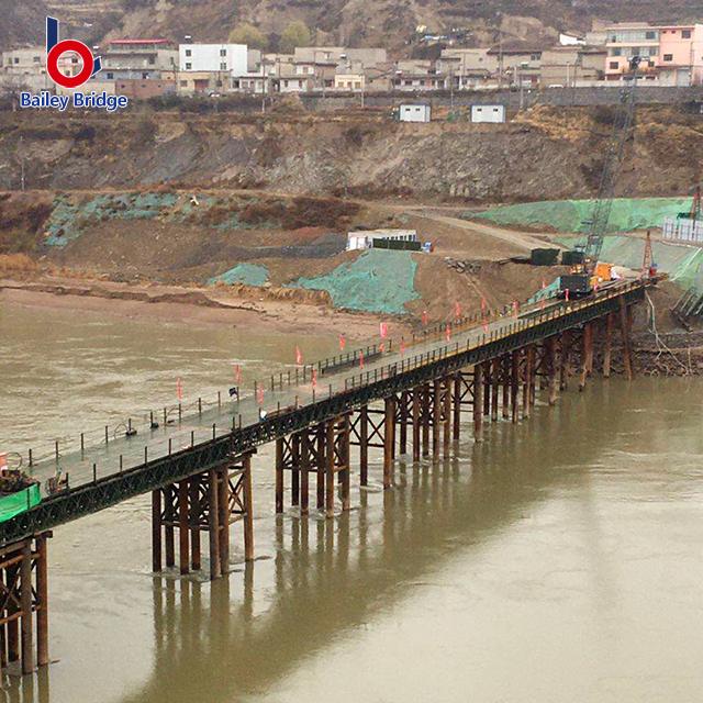
Modern engineering relies heavily on standardization. Standardizing strength allows for incredibly rapid rollout. The bailey truss bridge stands as a prime example of this innovation. You can pre-fabricate identical steel panels in a factory. Teams then pin these panels together on-site to reach the exact required length.
Modular capabilities solve complex logistical nightmares. You can deploy them anywhere. Let us examine primary deployment scenarios:
Disaster Relief: Floodwaters frequently wash out rural infrastructure. Emergency teams quickly deploy modular panels to reconnect stranded communities.
Emergency Detours: Major highway repairs require temporary bypasses. Modular panels carry heavy commercial traffic while crews fix the main route.
Logging Roads: Forestry operations push deep into the wilderness. They require sturdy crossings for heavily loaded timber trucks.
Remote Construction Access: Mining companies and dam builders need temporary heavy-duty access across remote ravines.
Standardized modular designs lower major site-prep barriers. You can transport the individual steel parts in standard commercial trucks. You do not need oversized load permits. Teams assemble the structure using simple hand tools and basic equipment. Many designs use a cantilever launching method. Crews build the structure on dry land. They use rollers to push it slowly across the gap. You do not need heavy lifting cranes. You do not need expensive barges in the river below.
Choosing the correct structural architecture dictates project success. We must align physical capabilities with budget and site constraints. Use the framework below to guide procurement discussions.
Evaluation Criteria | Solid Beam Specifications | Skeletal/Truss Specifications |
|---|---|---|
Optimal Span Range | Short spans (Under 50-80 feet) | Medium to long spans (80 to 300+ feet) |
Dead Weight Penalty | Extremely high over long distances | Very low (high strength-to-weight ratio) |
Fabrication Complexity | Low (Standard mill outputs or pours) | High (Numerous joints and welds) |
Aerodynamic Stability | Poor (Solid face catches high wind) | Excellent (Wind passes through webbing) |
Inspection Burden | Low (Simple monolithic surfaces) | High (Requires checking dozens of nodes) |
Solid structures excel in specific, limited environments. You should specify them for short spans. They work perfectly for distances under 50 to 80 feet. They fit projects operating under tight upfront fabrication budgets. You avoid paying for highly specialized welding labor. They also serve well when you face low vertical clearance requirements. A flat slab takes up very little vertical space.
Furthermore, consider your ongoing maintenance logistics. Specify solid structures in environments where ongoing joint maintenance is logistically prohibitive. If you cannot easily send inspection crews to check hundreds of steel bolts, avoid complex webbing.
Skeletal geometry dominates long-distance engineering. You must specify it for medium-to-long unsupported spans. Environmental constraints often prohibit building mid-river concrete piers. Deep water or fast currents make center supports impossible. You need a structure that can clear the entire gap at once.
You also need them for high live-load requirements combined with strict foundation weight limits. Weak soil cannot support the massive dead weight of a solid concrete structure. A skeletal design keeps the foundation loads manageable while carrying heavy freight. Finally, choose them for scenarios requiring rapid, modular assembly. Leveraging standardized bailey-style components saves months of construction time.
A truss design mathematically disperses stress rather than simply trying to resist it with massive bulk material. It converts destructive bending moments into manageable tension and compression. This geometric advantage eliminates the heavy dead zone found in solid structures. It is inherently stronger over distance. Project managers secure vastly longer unsupported spans while maintaining crucial aerodynamic stability.
Recommend your procurement teams and project managers move forward systematically. First, define your exact span requirements and vertical clearance limits. Second, conduct thorough geotechnical evaluations to determine your abutment strength and soil capacity. Finally, consult structural engineers to run specific live-load simulations. You must complete these steps before finalizing any formal Request for Proposal.
A: A triangle cannot be deformed by stress without altering the length of one of its sides. Unlike a rectangle, which easily skews into a parallelogram under lateral pressure, a triangle maintains its rigid angles. This unique geometric property ensures rigid force transfer and extreme stability under heavy loads.
A: They use significantly less raw material, which saves upfront purchasing costs. However, they require highly skilled labor for complex joint fabrication, welding, and assembly, which adds significant cost. The real return on investment is realized on longer spans where solid structures become impossibly expensive.
A: They carry higher maintenance demands due to numerous joints requiring regular fatigue and corrosion inspections. They are susceptible to localized damage; if one critical steel member fails, the entire structure is compromised. Additionally, "through-truss" designs impose strict overhead clearance limits for tall vehicles.
A: Yes. While originally designed for military and temporary emergency use, modern galvanized bailey bridges are extremely durable. Engineers frequently certify these modular steel structures for decades of permanent commercial use, particularly in rural environments, logging routes, and developing transport networks.
