Tel: +86 15262904857 E-mail: overseas@jsbaileybridge.com
- All
- Product Name
- Product Keyword
- Product Model
- Product Summary
- Product Description
- Multi Field Search


Views: 0 Author: Site Editor Publish Time: 2026-09-24 Origin: Site


Transitioning from the procurement of a bailey bridge to physical deployment introduces significant engineering and logistical risks. While their modular design allows for rapid assembly, selecting an incorrect installation method can quickly lead to project delays, cost overruns, or catastrophic structural failures. Every gap presents unique challenges. You must account for terrain physics, equipment access, and varying payload demands before breaking ground. This guide evaluates the standard installation methodologies available today. We frame the operational requirements, terrain constraints, and essential risk mitigation strategies required to execute a safe and compliant deployment. You will learn how to assess site conditions properly. We will help you balance labor constraints against heavy equipment usage. Ultimately, this framework empowers you to finalize a methodology tailored precisely to your crossing scenario.
The **Cantilever Launching Method** remains the industry standard for crossing gaps without requiring heavy machinery on the opposite bank, though it demands significant rear-clearance space.
**Crane Hoisting** offers the fastest deployment for a steel bailey bridge but is strictly limited by road access, soil bearing capacity, and equipment mobilization costs.
Method selection must be dictated by a rigorous site survey, evaluating gap width, bank elevation differentials, and load classification requirements (referencing standards such as FM 5-277).
Risk mitigation during installation requires precise calculations for counterweights, launching noses, and roller placement.
Defining business and engineering prerequisites is mandatory before committing to an assembly method. Terrain profiles significantly restrict your methodology options. You must assess bank stability and soil bearing capacity carefully. Base plates require solid ground to distribute massive structural loads effectively. Always determine the available staging area on the home bank beforehand. A confined workspace eliminates certain launch techniques immediately.
Planners routinely balance tight project timelines against steep equipment costs. Heavy cranes carry remarkably high mobilization fees. In contrast, semi-manual roller launches require longer labor hours. However, they drastically reduce your dependence on specialized machinery. You must verify your chosen method aligns with standard load classifications. The US Army Field Manual (FM 5-277) provides an authoritative framework here. Structural tolerance limits during the launch phase ultimately dictate engineering compliance.
Site Evaluation Parameters
Evaluation Metric | Critical Thresholds | Required Action |
|---|---|---|
Soil Bearing Capacity | > 200 kPa for heavy outriggers | Perform core sampling and geotechnical testing. |
Bank Elevation Differential | < 5% grade difference | Use a laser level survey to confirm abutment heights. |
Staging Area Length | Equal to total bridge length | Clear obstacles and grade the rear assembly zone. |
Assemble the structure on rocking rollers located on the near bank. Push it progressively across the gap using a lightweight launching nose. This technique thrives in challenging topographies. It presents the ideal use case for deep ravines and fast-flowing rivers. It works perfectly when heavy machinery cannot access the far bank. The primary advantage eliminates the need for massive lifting equipment entirely. Furthermore, the process remains highly scalable for various span lengths.
The major limitation involves significant rear space requirements. You need a staging area behind the abutment equal to the entire bridge length plus the launching nose. Miscalculating the balance point introduces severe structural risk. Proper counterweight calculations remain absolutely essential. If launching rollers fail under progressive weight, catastrophic structural tipping can easily occur.
Follow these standard sequence steps during a cantilever launch:
Assemble the launching nose using lightweight skeleton panels.
Place rocking rollers precisely aligned on the home bank abutment.
Connect the main bridge panels to the rear of the launching nose.
Push the structure forward incrementally using winches or manual labor.
Engage the receiving rollers on the far bank.
Remove the launching nose and jack the bridge down onto permanent bearings.
Always double-check roller alignments before initiating the push. A misaligned roller can jam the bottom chord of the panels. This forces the assembly team to halt operations and re-jack the structure mid-launch.
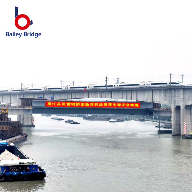
Fully or partially assemble the steel bailey bridge on solid ground. Use single or dual heavy-duty cranes to lift it. Position the modular structure directly onto the pre-built abutments. This method suits highway overpasses and urban emergency replacements perfectly. Short-span gaps with hardened access roads also benefit greatly from this approach.
The primary advantage maximizes the sheer speed of installation. It completely minimizes the need for a launching nose. You also avoid managing extensive rear counterweights. However, the core limitation centers on prohibitive mobilization costs. You need stable ground capable of supporting 50-ton crane outriggers safely. Soft mud or uncompacted gravel will cause outrigger failure during the lift.
Implementation realities require meticulous rigging plans. Spreader beams prevent chassis warping during the lift. They also stop the modular panels from twisting mid-air. Synchronizing dual cranes demands exceptional communication between operators.
Verify lifting capacities: Account for the weight of the rigging gear alongside the bridge panels.
Check wind speeds: Suspended bridge panels act as massive sails. Never hoist during high winds.
Use taglines: Ground crews must control the suspended load using heavy-duty ropes.
Utilize floating pontoons or barges to support the span. Crews build the structure and push it across wide water bodies incrementally. This approach suits extremely wide river crossings perfectly. In these massive scenarios, standard cantilever launching exceeds safe structural deflection limits. The key advantage bypasses standard maximum span limitations entirely. Unsupported launches simply cannot cover such distances safely.
However, the floating method remains highly vulnerable to natural forces. Fast water currents and tidal changes threaten stability constantly. Severe weather conditions can halt the operation without warning. Implementation realities demand continuous aquatic stabilization. You must anchor the barges securely against the river current.
Precise synchronization between bank-side assembly and water-based positioning guarantees success. Teams must adjust pontoon buoyancy as the bridge weight increases. Pumping water into or out of ballast tanks keeps the deck level. Failing to manage buoyancy correctly places immense shear stress on the panel joints. Always monitor weather reports diligently before initiating a floating installation.
Adhere strictly to established military and civil engineering standards. US Army Field Manual principles (FM 5-277) dictate proper assembly sequencing. These authoritative frameworks ensure personnel safety at every stage. Monitor the sag of the launching nose continuously. Gravity pulls the unsupported front end downward as it crosses the gap. Ensure it successfully engages the far-bank receiving rollers without buckling. If the nose hits the abutment face, adjust your jack heights immediately.
Transitioning to permanent maintenance involves specific post-installation protocols. You must seat the bridge onto its bearings carefully. Use synchronized hydraulic jacks to lower the structure evenly. Check all panel pin tolerances to confirm structural rigidity. A loose pin compromises the entire load-bearing capacity.
Establish a routine inspection schedule immediately after deployment. Active maintenance ensures long-term operational performance. Inspect transoms, sway braces, and deck plates monthly. Re-torque any loosened bolts discovered during these routine checks. A proactive safety culture prevents minor wear from escalating into major structural failure.
Evaluate a cost-to-outcome matrix carefully. You must weigh labor hours against equipment rentals. Cantilever launching requires extensive manpower but minimal machinery. Crane hoisting demands expensive rentals but accelerates deployment dramatically. Vetting installation contractors prevents costly deployment errors. Ask potential partners about their specific field experience. They should understand distinct load classes and complex terrain types.
Request examples of spans similar to your project dimensions. Initiate a geotechnical site survey as your immediate next step. Request method-specific CAD schematics from your structural manufacturer. Visualizing the deployment sequence helps identify logistical bottlenecks early.
Cost-to-Outcome Matrix Chart
Installation Method | Speed of Deployment | Labor Intensity | Equipment Cost | Best Terrain Match |
|---|---|---|---|---|
Cantilever Launching | Moderate (Days) | High | Low | Deep ravines, remote areas |
Crane Hoisting | Fast (Hours) | Low | High | Urban areas, highway passes |
Pontoon-Assisted | Slow (Weeks) | High | Moderate | Wide rivers, tidal zones |
Take these actionable next steps to finalize your project. First, secure a certified soil report for both bank abutments. Second, draft a comprehensive risk assessment covering local weather patterns. Third, consult with your bridge manufacturer to verify the exact counterweight formulas required for your specific span.
The right installation method is rarely a matter of preference. Terrain physics dictates your final operational choices. Budgetary constraints and access limitations also play major roles in the decision process. Cantilever launching remains the most versatile approach globally. It solves access problems efficiently. Crane hoisting offers unmatched speed where sites remain fully accessible to heavy transport. Pontoon launches conquer wide rivers that defy conventional bridging.
To execute a flawless installation, follow these critical steps:
Conduct a rigorous geotechnical survey of both landing banks.
Calculate your exact staging area dimensions before ordering parts.
Align your load class requirements with recognized standards like FM 5-277.
Develop a precise counterweight and rigging plan.
Always consult with a certified bridge engineer. Ask your structural manufacturer to conduct a thorough feasibility study. Finalize your deployment blueprints before mobilizing any field crews to the site.
A: The general rule requires a staging area equal to the total length of the bridge plus the length of the launching nose. This space allows crews to assemble panels and attach counterweights safely. However, site-specific engineering calculations remain mandatory to verify exact clearance dimensions.
A: Installation timeframes depend entirely on the chosen method. Cantilever methods generally take several days when executed by trained crews. Conversely, crane-lifted pre-assembled spans can be hoisted and secured in a matter of hours, assuming site preparation is already complete.
A: Yes, baily bridges can be installed using minimal equipment. Rollers, hydraulic jacks, and sheer manpower can execute a cantilever launch successfully. However, incorporating light mechanical assistance like power winches represents the modern standard for improving site safety and efficiency.
A: Uneven banks require extensive site preparation before installation begins. Crews use specialized timber cribbing and adjustable base plates to level the staging zone. Proper terrain grading is an absolute prerequisite prior to placing the launching rollers to prevent structural misalignment.
