Tel: +86 15262904857 E-mail: overseas@jsbaileybridge.com
- All
- Product Name
- Product Keyword
- Product Model
- Product Summary
- Product Description
- Multi Field Search


Views: 0 Author: Site Editor Publish Time: 2026-07-31 Origin: Site


Bridge stability transcends basic physics textbooks. For infrastructure developers, it directly dictates load ratings, shapes maintenance schedules, and determines overall project viability. A poorly selected structure risks costly delays and severe safety hazards. The intrinsic stability of a truss bridge stems from its geometric reliance on triangles to distribute force. This unique geometry makes it incredibly efficient at maximizing load capacity while significantly minimizing material weight.
Understanding these mechanical forces connects structural design directly to procurement decisions. You will discover how this knowledge helps project managers choose the right bridge configuration for their site, budget, and timeline. We will explore core mechanics, assess load capacities, and examine standard modular configurations. Finally, you will learn how to navigate implementation realities and shortlist the ideal solution for your next infrastructure rollout.
Geometric rigidity: Triangulation effectively converts vertical loads into axial forces (tension and compression), preventing structural bending.
High strength-to-weight ratio: The design requires less raw material to achieve high load ratings, directly lowering procurement and foundation costs.
Modular versatility: Configurations like the bailey truss bridge offer standardized, prefabricated components that drastically reduce deployment timelines.
Maintenance considerations: The high number of joints and connections requires rigorous, scheduled inspections for localized corrosion and material fatigue.
You cannot distort a triangle without altering the length of its sides. Unlike squares or rectangles, triangles possess intrinsic geometric rigidity. If you push the corner of a square, it easily collapses into a parallelogram. To collapse a triangle, you must physically crush or snap its constituent structural members. This physical reality forms the fundamental baseline of truss engineering.
This framework excels at managing complex force distribution. When commercial traffic crosses a span, it applies a dynamic live load. The steel members themselves create a constant dead load. The structural lattice channels these downward forces along straight linear paths. Engineers call these axial forces. Some members stretch outward. They experience tension. Other members push inward against each other. They experience compression.
By channeling stress into pure tension and compression, we successfully eliminate severe bending moments. Traditional beams handle weight by bending, which concentrates massive stress near the center of the span. Because forces remain axial in a triangulated framework, individual steel members do not bend significantly. They simply pull or push along their primary axis. This behavioral shift drastically reduces the risk of catastrophic mid-span failure. It keeps the entire structural system predictable under heavy stress.
Project managers must define clear success criteria before selecting a design. You must know exactly where triangulated frameworks outperform traditional beam or suspension alternatives. Short rural crossings often rely on basic steel beams. Massive over-water highways demand complex suspension cables. The intermediate span represents the ideal territory for triangulated engineering.
Optimal span ranges generally fall between 50 and 300 feet for simple spans. Continuous designs can stretch much further by resting on intermediate piers. Structural engineers favor this range because it offers the highest return on material investment. You achieve maximum rigidity without paying for unnecessary steel mass.
Structural Performance Chart
Bridge Type | Optimal Span Range | Load Efficiency Rating | Primary Force Mechanism |
|---|---|---|---|
Standard Beam | Up to 50 feet | Low to Medium | Bending |
Standard Truss | 50 to 300 feet | High | Axial Tension / Compression |
Continuous Truss | 300 to 1,000+ feet | High | Distributed Axial Load |
Suspension | 2,000+ feet | Medium (Dead Load Heavy) | Cable Tension |
Live versus dead load efficiency drives the true commercial value of these structures. The superstructure remains inherently lightweight. Because it weighs less, it does not expend its own structural capacity merely supporting itself. This allows a much higher percentage of the total capacity to support live operational loads. You can move heavier machinery, denser commercial traffic, and larger freight across the same gap. This efficiency proves critical for logging operations, mining sites, and heavy industrial detours.
Engineers have developed several standard configurations over the last century. The Pratt, Warren, and Howe designs remain the most prominent. They manipulate diagonal alignments to optimize specific material uses or load centers.
The Pratt layout features diagonal members sloping toward the center of the span. This alignment places the longer diagonal pieces in tension and the shorter vertical pieces in compression. It optimizes steel usage beautifully. The Howe layout reverses this approach. Its diagonals slope away from the center. This places diagonals in compression, making it historically ideal for heavy timber construction. The Warren layout uses alternating equilateral triangles. It handles both tension and compression well, making it highly versatile for modern steel fabrication.
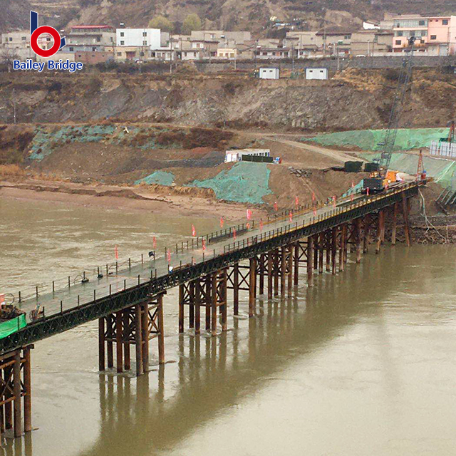
The bailey truss bridge highlights a highly specialized modular category. Engineers designed it as a portable, pre-fabricated system. It utilizes standardized, interchangeable steel panels linked by high-strength pins. You do not need custom fabrication for every new site.
We evaluate this modular solution based on rapid deployment capabilities. It proves ideal for disaster relief, temporary detour routes, or highly remote locations. Heavy lifting equipment often cannot reach these isolated sites. Crews can assemble these interchangeable panels by hand. They push the completed sections over the gap using a cantilever launching method. This eliminates the need for massive cranes, solving complex logistical nightmares for rural developers.
Material efficiency heavily influences initial capital expenditures. Using less solid mass directly reduces raw material purchases. You buy less steel per foot of crossing. This lightweight profile generates a cascading financial benefit. Lighter superstructures exert less downward force on their foundations. You can lower the necessary scale of concrete abutments and intermediate piers. Smaller foundations require less excavation, less concrete, and fewer labor hours.
Prefabrication generates massive advantages for project rollout speed. Factories manufacture components in controlled indoor environments. Automated welding machines produce highly consistent joints. Weather delays do not affect factory production. Trucks deliver the modular sections precisely when the site is ready. Crews bolt or pin them together rapidly.
Reduced site disruption: Fast assembly limits environmental impact over sensitive waterways.
Lower labor demand: Minimal on-site welding reduces the need for highly specialized field labor.
Predictable scheduling: Off-site manufacturing isolates the project timeline from unpredictable field variables.
Predictable lifecycle management serves as another major advantage. Structural engineers rely on highly proven mechanics. They use established software to accurately model material fatigue and lifespan constraints. Every connection behaves predictably under stress. This transparency allows infrastructure managers to plan capital replacements accurately. You avoid surprise failures by adhering to mathematical modeling.
Despite their efficiency, these frameworks carry specific structural vulnerabilities. Connection points demand intense scrutiny. Every single gusset plate, bolt, and weld acts as a potential site for localized fatigue. When loads cross the span, these joints absorb massive cyclical stress. If a single primary gusset plate fails, the surrounding geometry can destabilize rapidly. Industry standards mandate rigorous, hands-on inspections to monitor these vital connections.
Corrosion management presents a continuous operational challenge. The intricate lattice design creates a vast amount of surface area. It exposes far more steel to rain, snow, and road salt compared to a solid concrete beam. You must apply robust anti-corrosion coatings during fabrication. Zinc-rich epoxies and galvanized finishes provide excellent baseline protection.
Apply multi-coat protective paint systems immediately after fabrication.
Schedule routine power-washing to remove corrosive de-icing salts.
Inspect horizontal structural ledges where debris and standing water frequently accumulate.
Touch up localized paint failures before surface rust penetrates the steel substrate.
Clearance limitations dictate specific route restrictions. Many designs utilize a through-truss configuration. Traffic literally drives through the structural cage. You must carefully evaluate both vertical and horizontal clearance. Oversized agricultural machinery or oversized industrial freight might strike overhead portal bracing. A lateral impact from a wide load can severely damage crucial load-bearing verticals. Always verify long-term traffic profiles before committing to a restrictive cage design.
Your procurement journey must start with a thorough site and geotechnical assessment. These rigid frameworks transfer significant concentrated loads directly to their end supports. If the soil at the riverbank is soft, the abutment might settle unevenly. Uneven settling induces dangerous stress across the rigid steel framework. You must verify soil bearing capacity before ordering any structural steel.
Project managers often struggle to choose between bespoke designs and standardized systems. The matrix below outlines how to evaluate your options.
Custom vs Modular Selection Matrix
Evaluation Metric | Custom Architectural Build | Standard Modular System |
|---|---|---|
Design Flexibility | High (Tailored aesthetics and curves) | Low (Fixed standardized panels) |
Deployment Speed | Slow (Months of field assembly) | Fast (Days to weeks) |
Equipment Needs | Heavy cranes required | Minimal (Cantilever launching possible) |
Primary Application | Permanent urban highways | Detours, rural roads, logging, emergency |
We strongly recommend engaging structural consultants early in the planning phase. They bring necessary modeling software to validate your initial assumptions. Consultants will calculate localized wind loads, map historical seismic activity, and evaluate specific heavy-haul requirements. Their early involvement prevents costly redesigns and ensures full compliance with local transportation authority standards.
The core stability of this structural style roots itself entirely in simple triangulation. This basic geometric principle translates into highly predictable, scalable, and resilient infrastructure. You can maximize site efficiency by channeling forces safely along straight linear members. We achieve impressive load ratings without pouring massive concrete structures.
However, successful implementation demands a balanced view of the system. You must weigh the exceptional strength-to-weight ratios against the strict reality of long-term joint maintenance. Proper planning ensures decades of safe operation.
Execute a deep geotechnical survey to validate abutment settling tolerances.
Calculate strict vertical and horizontal clearances if utilizing a through-truss design.
Develop a rigorous, funded inspection schedule focusing heavily on gusset plates and lower chord moisture accumulation.
Match the urgency of your timeline to the right modular or custom system.
A: Triangles are the only polygons that hold their shape under pressure without their joints being rigid. They naturally convert applied vertical loads into purely axial forces (push or pull). This prevents the structural members from bending, ensuring maximum geometric stability and material efficiency.
A: Individual simple-span trusses are highly effective and economical up to 300 feet. However, continuous configurations can safely span much greater distances. By resting the continuous framework on multiple intermediate concrete piers, engineers can easily bridge gaps exceeding 1,000 feet.
A: Yes. While originally designed for temporary military deployment during World War II, modern bailey-style components utilize high-grade galvanized steel. Transportation departments frequently install them as permanent solutions in rural areas, logging routes, and municipal applications where rapid deployment is highly valued.
