Tel: +86 15262904857 E-mail: overseas@jsbaileybridge.com
- All
- Product Name
- Product Keyword
- Product Model
- Product Summary
- Product Description
- Multi Field Search


Views: 0 Author: Site Editor Publish Time: 2026-07-22 Origin: Site


How much weight can a temporary bridge safely carry? The answer is rarely one simple number.
A bailey bridge uses modular steel panels and adjustable truss arrangements. Its capacity changes according to span, width, vehicle type, and structural configuration.
This article explains typical capacity ranges, major design factors, and practical selection steps.
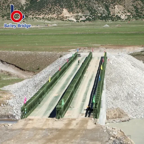
● A bailey bridge does not have one universal load capacity. Its rating depends on span length, truss arrangement, reinforcement, deck design, and foundation conditions.
● A bridge designed for ordinary road traffic may target a load near 40 tons. Heavier construction projects may require capacities of 80 tons or more.
● Specialized modular bridges can support approximately 100 to 120 tons. However, these capacities require wider, reinforced, or multi-row structures.
● Longer spans usually reduce the available vehicle load. Engineers may add more trusses, deeper structures, reinforcement, or intermediate supports.
● Gross vehicle weight alone is not enough. Axle loads, axle spacing, vehicle speed, crossing frequency, and load distribution also matter.
● Load signs, inspections, speed controls, and scheduled maintenance help preserve safe performance throughout the bridge’s service life.
A typical load rating depends on what the bridge must carry. There is no standard tonnage suitable for every project.
For light pedestrian or service access, the required capacity may remain relatively low. Rural roads, emergency routes, and construction access usually require stronger designs. A published temporary access project used a bridge carrying a 40-ton design load across a span of almost 40 meters. This example shows how a moderate vehicle load can be supported over a relatively long crossing.
For many road and construction projects, a planning range near 40 to 80 tons may be more realistic. The lower end can serve loaded trucks, buses, or ordinary equipment. The upper end may accommodate heavier construction vehicles or frequent commercial traffic.
The manufacturer also reports a reinforced bridge supporting 80 tons across a 21-meter span. Reinforcing chords allowed the structure to increase capacity while maintaining a relatively efficient truss arrangement.
Special projects may need much more capacity. One customized bridge was designed for a 120-ton load across a 24-meter span. It used several parallel truss rows to distribute large transport loads. The bridge supported oversized renewable energy equipment and heavy construction vehicles.
These examples do not create universal ratings. They show how modular structures can be adapted to different loads.
Application Level | Illustrative Capacity | Typical Traffic |
Light access | Project-specific low load | Pedestrians and utility vehicles |
Standard road access | Around 40 tons | Trucks, buses, and relief vehicles |
Heavy construction access | Around 60–80 tons | Excavators and loaded construction trucks |
Specialized equipment transport | 100–120 tons or more | Cranes, industrial modules, and oversized equipment |
The figures above are early planning references. They are not final design limits. Every bridge requires calculations based on its actual span, configuration, and loading conditions.
Note: Never select a bridge using gross tonnage alone. Ask for a capacity calculation based on the actual vehicle arrangement.
Load capacity describes the maximum approved load a bridge can carry under defined conditions. However, the stated figure may represent several different loading situations.
Gross vehicle weight includes the vehicle, fuel, passengers, cargo, and attached equipment. For equipment transport, it must also include the trailer or transporter.
A 60-ton machine does not create only a 60-ton bridge load. Its transporter may add considerable weight. The complete moving load must be included.
Two vehicles may have the same gross weight but create different structural demands. A vehicle with closely spaced heavy axles creates stronger local forces.
Axle loads affect the deck, stringers, transoms, and trusses. Engineers therefore need individual axle weights and the distance between them.
A parked vehicle creates a static load. A moving vehicle creates additional dynamic effects.
Braking, acceleration, surface unevenness, and impact can increase structural stress. Higher speeds may create stronger dynamic forces. Safe ratings often include allowances for these effects.
Wheeled vehicles place loads through several tire contact areas. Tracked equipment spreads weight across a longer surface.
However, tracked machines can still create high local forces during turning or braking. Engineers must assess the actual contact pattern and movement plan.
Tip: Send a vehicle drawing showing total weight, axle weights, axle spacing, and tire or track dimensions.
Span length means the unsupported distance between bearing points. It is one of the strongest influences on capacity.
As the span increases, the bridge carries more of its own weight. The bending forces also become greater. As a result, the same truss arrangement normally carries less live traffic across a longer span.
A short reinforced bridge may support very heavy equipment. The same structure may not support that equipment over a much longer crossing. More panels increase length, but they also add dead weight.
Longer spans often require additional truss rows or stacked panels. Reinforcing chords may also strengthen highly stressed areas. The manufacturer explains that parallel panel rows and vertically stacked panels allow engineers to scale both span and capacity.
Site conditions can also limit the available span. Weak riverbanks may need stronger abutments. Soft soil may require piles or other foundation systems. Deep water may prevent intermediate support installation.
Where conditions allow, engineers can divide a long crossing into several shorter spans. Intermediate piers reduce the unsupported distance. This approach may improve load performance and control deflection.
However, piers add foundation work and environmental concerns. They may also obstruct floodwater, debris, or navigation. The final choice must balance capacity, installation, and site risk.
A bailey bridge gains much of its flexibility from standardized modular components. Engineers can change its strength without redesigning every individual part.
Adding truss rows beside each other increases the amount of steel resisting the load. This arrangement can improve bending and shear capacity.
A basic bridge may use fewer rows for light traffic. Heavy industrial crossings may use several parallel trusses under or beside the roadway.
More rows do not always share the load equally. Inner trusses may carry greater forces than outer trusses. Engineering analysis must confirm the real distribution.
Stacking panels creates a deeper truss. Greater structural depth can improve stiffness and bending resistance.
This method is useful for longer spans or heavier loads. However, it adds components, weight, assembly time, and transport volume.
Reinforcing chords strengthen areas carrying high tension or compression. They can raise capacity without requiring a completely different bridge system.
One published 80-ton application used reinforcement to achieve its required capacity over a 21-meter span. This example shows why configuration matters more than a general product label.
Some specialized bridges place several trusses directly below the roadway. This creates a wide platform without overhead truss restrictions.
Such structures can serve cranes, oversized equipment, or construction work platforms. Wider arrangements also help spread concentrated loads across several structural lines.
The correct configuration depends on the load path. Simply adding panels does not guarantee safe capacity. Connections, bracing, transoms, decks, and bearings must work together.
Structural configuration is important, but it is not the only factor. Several supporting conditions can raise or reduce practical capacity.
Panels, chords, pins, bolts, and welded joints must meet the design requirements. Material strength and manufacturing accuracy affect how forces move through the bridge.
The manufacturer describes its bridge systems as prefabricated structures using high-strength galvanized steel. Standardized components can be assembled, extended, or reconfigured for different spans and loads.
Poor tolerances may create uneven contact or unexpected stress. Damaged pins and distorted holes can also reduce connection performance.
A wider roadway uses more decking and supporting steel. This increases dead weight before any vehicle enters the bridge.
Deck thickness, wheel paths, anti-slip surfaces, and wearing layers also matter. Concentrated wheel loads may control deck design even when the main trusses remain adequate.
Bridge reactions pass through bearings and into foundations. A strong superstructure cannot correct weak abutments or unstable soil.
Settlement can change the bridge alignment and load distribution. Bearings must remain level, secure, and able to provide their intended movement or restraint.
A bridge carrying one heavy vehicle each month faces different demands from one carrying hundreds of loaded trucks daily.
Repeated loading can cause fatigue. Engineers must consider the number of expected crossings, service period, and traffic growth.
Wind, temperature, corrosion, flooding, seismic activity, and debris impact can affect performance.
Galvanized steel provides useful corrosion resistance, but it does not remove inspection needs. Damaged coatings should be repaired before corrosion spreads.
Note: Temporary use does not remove engineering requirements. Frequent traffic may create demands similar to permanent service.
Different applications create different load patterns. Understanding the operating purpose helps engineers select a suitable design.
Emergency bridges may carry ambulances, rescue trucks, utility vehicles, and supply convoys. Rapid installation matters, but the bridge must still support the heaviest expected vehicle.
Modular systems are widely used to restore access after floods, earthquakes, or road damage. Standardized components support fast assembly and later reconfiguration.
Traffic controls may limit speed or permit only one vehicle at a time. These controls can reduce risk during urgent operations.
Construction bridges may carry excavators, concrete trucks, cranes, loaders, and material transporters.
Their traffic often repeats throughout the day. Capacity decisions must consider fatigue, braking, mud buildup, and possible overloads.
Heavy crawler equipment may create concentrated loads. A wider supporting platform may be needed to distribute those forces.
Rural bridges may carry buses, agricultural equipment, delivery trucks, and local traffic.
The heaviest regular vehicle should guide the design. Seasonal harvest vehicles or fuel trucks may control capacity even when everyday traffic remains light.
Industrial projects may move turbines, transformers, mining machines, or large prefabricated modules.
These loads require detailed route studies. Engineers must check turning space, approach slopes, trailer clearance, axle groups, and bridge deflection.
A published 120-ton bridge application supported specialized transport vehicles carrying large energy equipment. It also provided access for cranes, excavators, and concrete mixers.
Choosing capacity begins before a bridge supplier prepares the design. Buyers should collect complete project information first.
Identify the heaviest vehicle expected during the entire project. Include trailers, cargo, tools, attachments, and counterweights.
Provide the following details:
● Total operating weight
● Individual axle loads
● Axle spacing
● Overall vehicle length and width
● Tire or track contact dimensions
● Travel speed
● Number of daily crossings
Future traffic should also be considered. A bridge designed only for current vehicles may become restrictive later.
Measure the clear distance between support points. Do not rely only on river width.
The bridge may need extra length for stable foundations. Roadway width, sidewalks, barriers, and clearance requirements also affect the structure.
State whether two vehicles may enter together. Explain whether vehicles will stop, turn, or brake on the bridge.
Traffic direction and spacing can significantly change the maximum simultaneous load.
Geotechnical information helps determine foundation reactions. Water level, flood history, wind exposure, temperature, and seismic requirements may affect the design.
Access conditions also influence installation. Remote sites may favor smaller modular components and simpler launching methods.
A technical proposal should show the span, width, truss arrangement, material specification, deck system, and foundation reactions.
It should also identify the design vehicle and applicable loading standard. Final drawings must match the bridge supplied to the site.
Tip: Request a clear load statement identifying gross weight, axle limits, permitted speed, and simultaneous vehicle restrictions.
A bailey bridge may support light traffic, standard trucks, or specialized loads above 100 tons. Its safe capacity depends on span, configuration, foundations, and vehicle details. Bailey Steel Bridge provides modular steel bridges, tailored engineering, manufacturing support, and installation guidance. Its adaptable systems help projects achieve reliable access, faster deployment, and practical long-term value.
A: A bailey bridge may carry about 40 tons, while reinforced designs support much more.
A: Yes. A customized bailey bridge can support 100 tons under approved conditions.
A: Longer spans increase bending forces and structural dead weight.
A: Engineers assess span, axle loads, configuration, foundations, and traffic conditions.
A: Usually. More steel, reinforcement, decking, and foundation work increase costs.
A: Overloading, loose connections, weak foundations, or incorrect assembly may cause it.


